WEEK
SIX
Electronic Design
Task for this week
Group Assignment
Use the test equipment in your lab to observe the operation of a microcontroller circuit board.Individual Assignment
Design a development board to interact and communicate with an embedded microcontroller.Group Assignment
Multimeter
In group assignment we have to test the lab equipments like multimeter, Oscilloscope and power supply. We started this test with multimeter.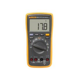
Multimeter is a device to check the AC & DC voltage, resistance value, capacitor value, continuity test, and current value. we start our test with 100k resistor. We set the our multimeter to resistor and check the value of resistor. Then we check the capacitor value.
multimeter is also used for to check the continuity of the circuit which help in find the break point. After this we start testing of Oscilloscope.
Oscilloscope
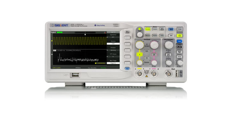
Oscilloscope is the big brother of multimeter. It shows the values in form of graph over time. It help in deep analyser of signal and its only way to see frequency. by multimeter we see only a number of frequency not a waveform of it. In todays technology everythings uses signal and digital world run on it, to Know the meaning of digital we have to understand the signal. signal can be read or seen in oscilloscope. We have two channel oscilloscope by which we can compare two signal at a time.
Click here to know more about group assignment.
My Individual Assignment
So I start I start my individual assignmnet by knowing basic electronic component.1.Resistor-
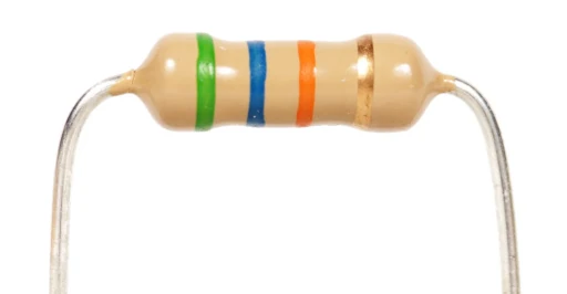
Resistor is electronic device which is used for control the flow of current and also used for provide a particular voltage to a component. The resisitor is made up
carbon, Metal and metal oxide. The unit of resistor is ohm. and it can be deteremine by following formula-Resistance(R)=Volt(V)/Current(I)
2.Capacitor-
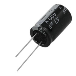
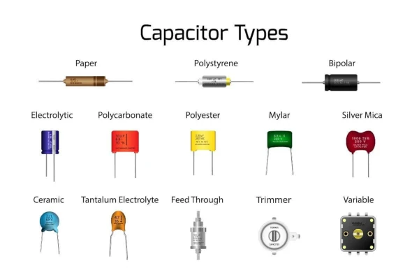
Capacitor is two terminal device and it is used for stored energy. inside the capacitor there are two elecric conductor and the gap betwwn them is filled by
dielectric medium.
polarized vs Non polarized capacitor- polarized Capacitor are those which can be used in one direction only. Non polarized Capacitor are
cane be used in any direction.
3.Diode-
The diodes are two terminal electric device which is made up of semiconductor. Diodes are used for supply the current in one direction and restrict the flowof current in another direction. They are also used for Convert AC supply in DC.
(i)Zener diode - This is semiconductor device which flow the current in forward direction or reverese direction. Reverse direction of current flow only when the
volatge reached a specified voltage.
(ii)Schkottkey- This is semiconductor device which is used for action of fast switching and low flow voltage drop.
(iii)LED - Led is Light Emitting dode Which produce light when voltage flow in it.
4.Transistor-
They are semiconductor device which is used for switching and amplifying the electrical siganl.5.Microcontroller-
Microcontroller is compact intigrated circuit which used in emebeded system to perform a specified task.6.Kirchoffs Law-
(a)Kirchoffs current law -
According to this law the cureent Flow inside the circuit is equal to current flow out of circle.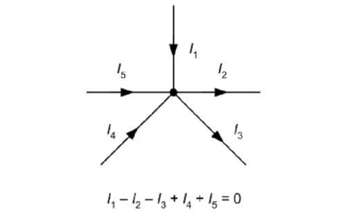
(b)kirchoffs voltage law-
According to this law the sum of voltage of a closed loop circuit is zero.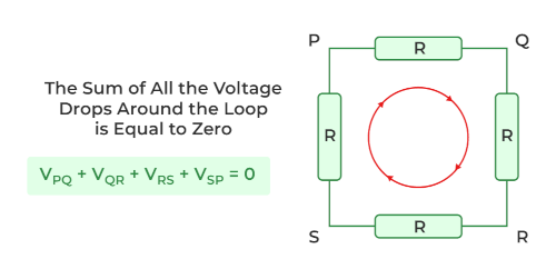
Component Used
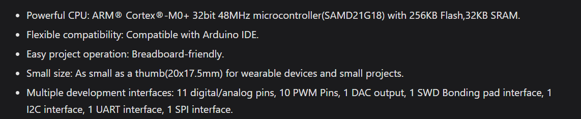
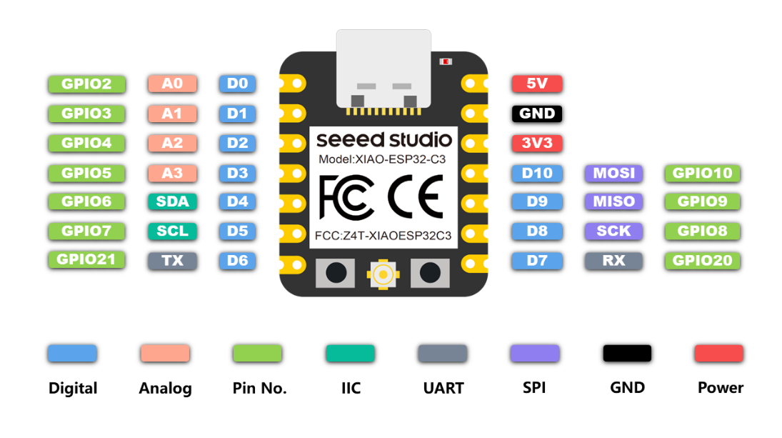
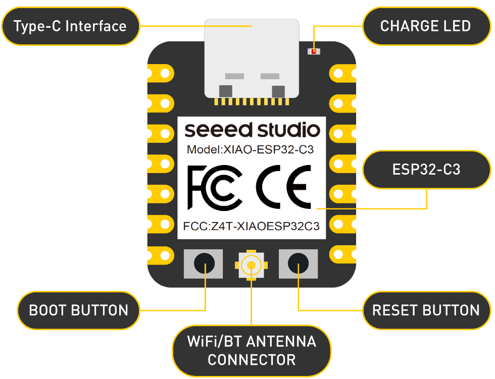
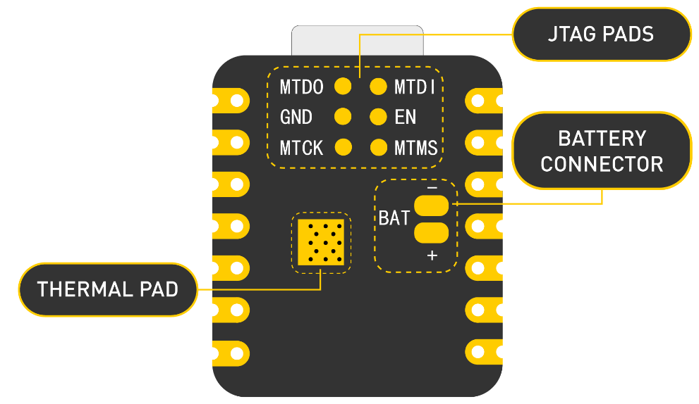
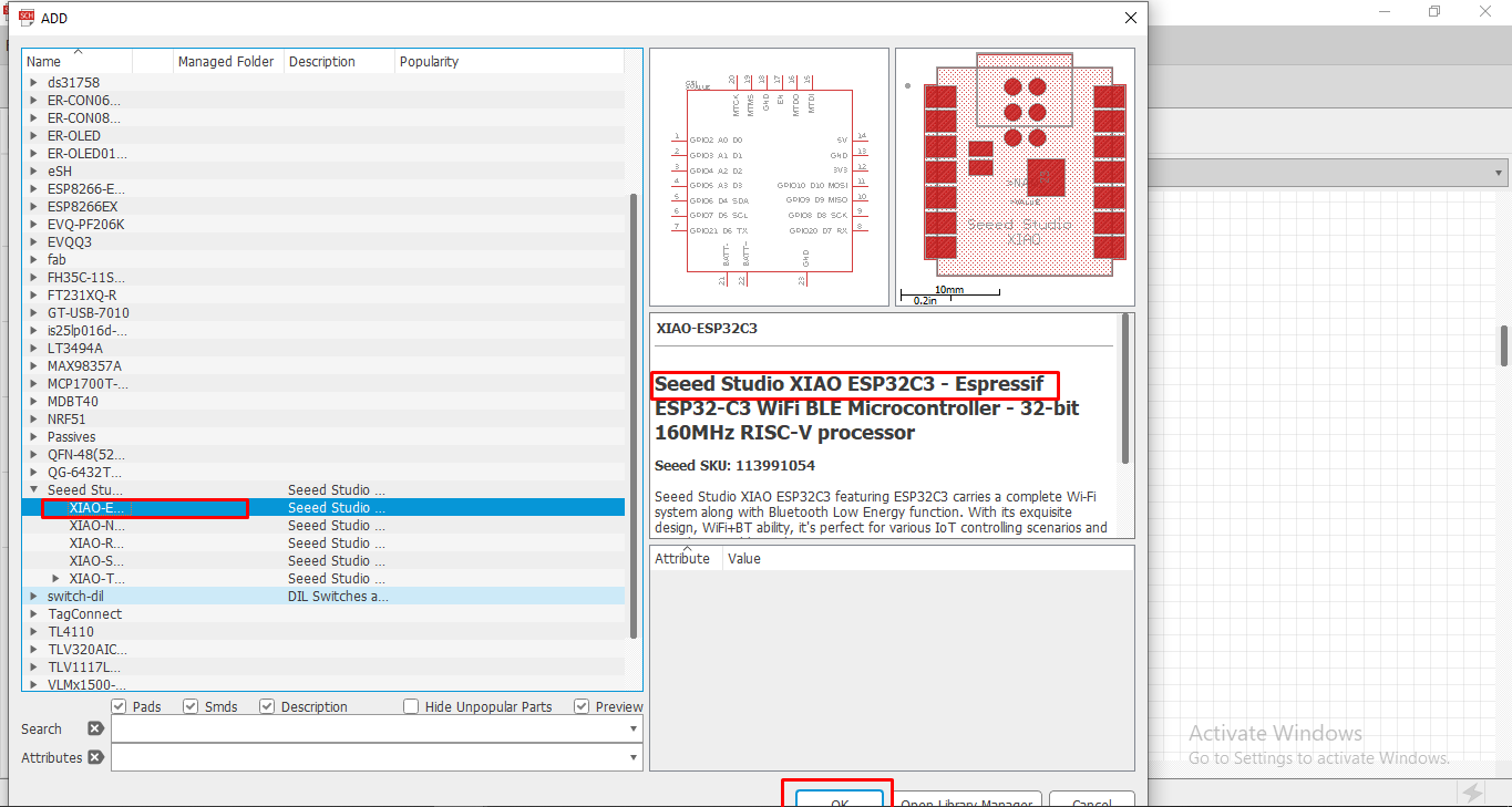
XIAO ESP32 Board
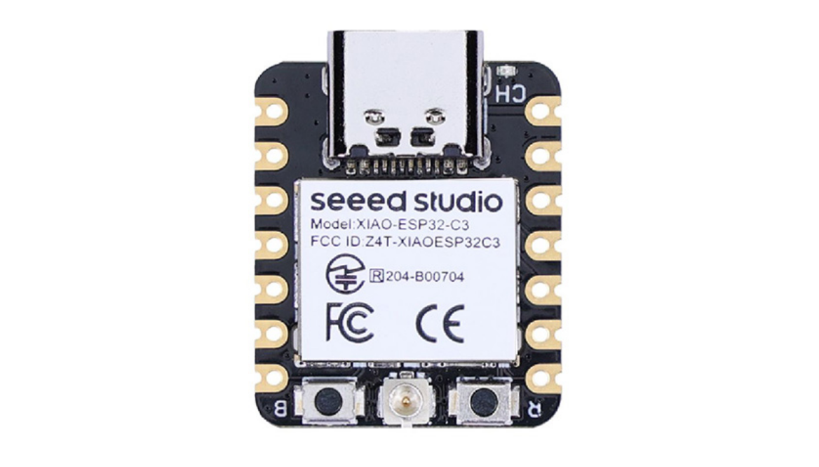
Xiao is a small but Powewrfull processore. Its size is just like our thumb. It have ESP32Ce Soc and RISCV single core 32 Bit Processor which operates on
160Mhz. The size of this Board is 21mm*17.5mm. The board required 5V to operate. Its tiny size make it very advance with the features.
This board have wireless connectivity lof WIFI and Bluetooth. It have 400Kb SRAM and 4mb Flash memory. This board also have an external antena which
enhance the wireless connectivity.
It have 1-UART, 1-IIC, 1-IIS , 1-SPI serial communication port. It have 11 GPIO Pins which also supports PWM and have 4 ADC pins. It consume
about 44 micron ampere in deep sleep mode. it consume about 25mA when wifi is enabled and consume 27mA when blurtooyh is enabled. It is used in IOT
project, low power consumed project etc.
Reference
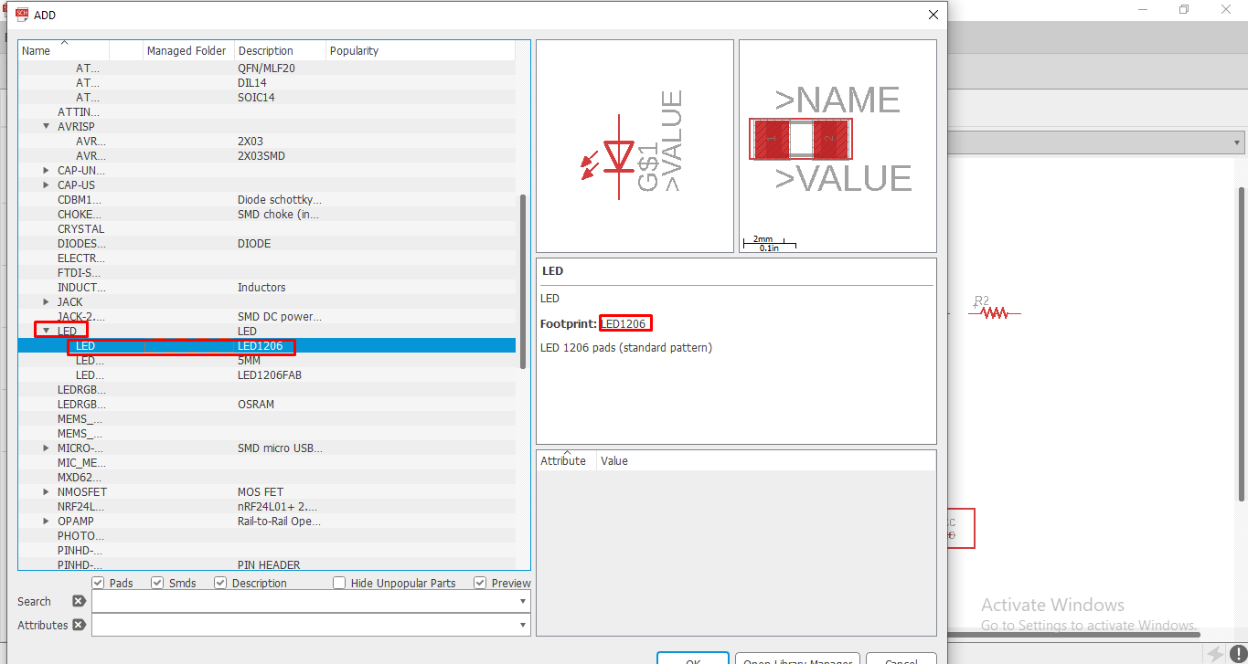
1206 package Led and resistor
1206-SMD LEDs
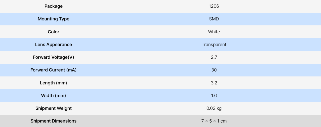
Here is the details of led.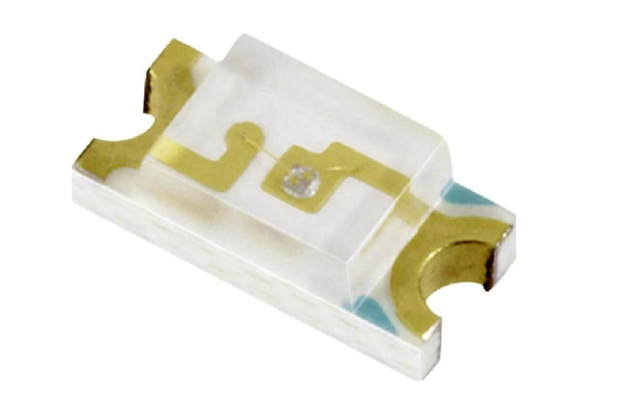
Reference
Resistor value calculation
Now we have calculate the resistor value for the Led. So to calculate the resistor value we need the some details of voltage and currentrequirement of the Led. So there is two to find this details. First one is to read the data sheet of the led and find this parameter value
and another one is calculate the parameter by using Multimeter. At this time I calculate the resistor by using data sheet of led.
From above Image we see the details of white Led. Which required the Current of 30mA and voltage of 2.7V (we take it 3V for blue and Green leds)
So for the calculation I am using Online resistor calculator and i put the value inside it. Then it gives the value of 100ohm for the LED.
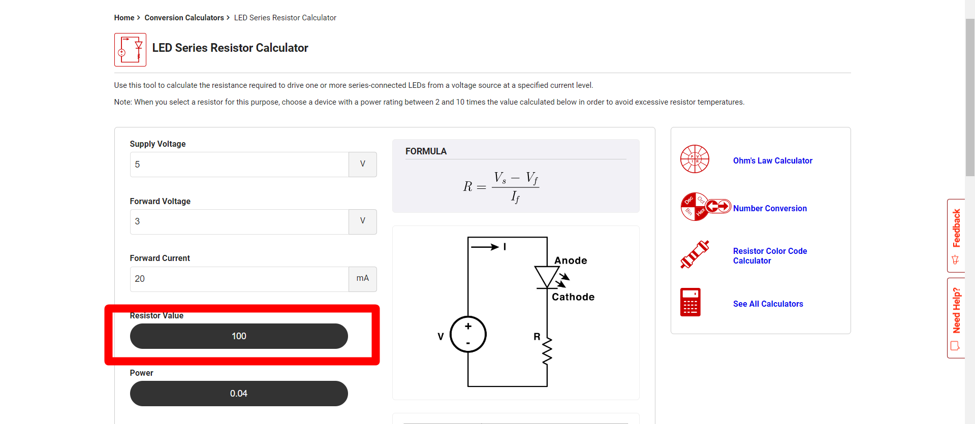
So the minimum Resistor value for the led is 100 ohm. We can also use resistor value of more than 100 ohm but its intensity of brightness
is reduced due to low current supply.
Click here to visit Digikey.in to calculate the resistor value.
PCB design
I have to design a pcb. So for this I chose eagle software. Eagle is owned by autodesk. You can download it from The autodesk website. After downloadlogin with your fusion 360 account Id password in Eagle.
Click here to download the software.
Schematic design
Open The eagle Software and then Follow the steps to create a new project work.Go to file >> New >> Project then Enter
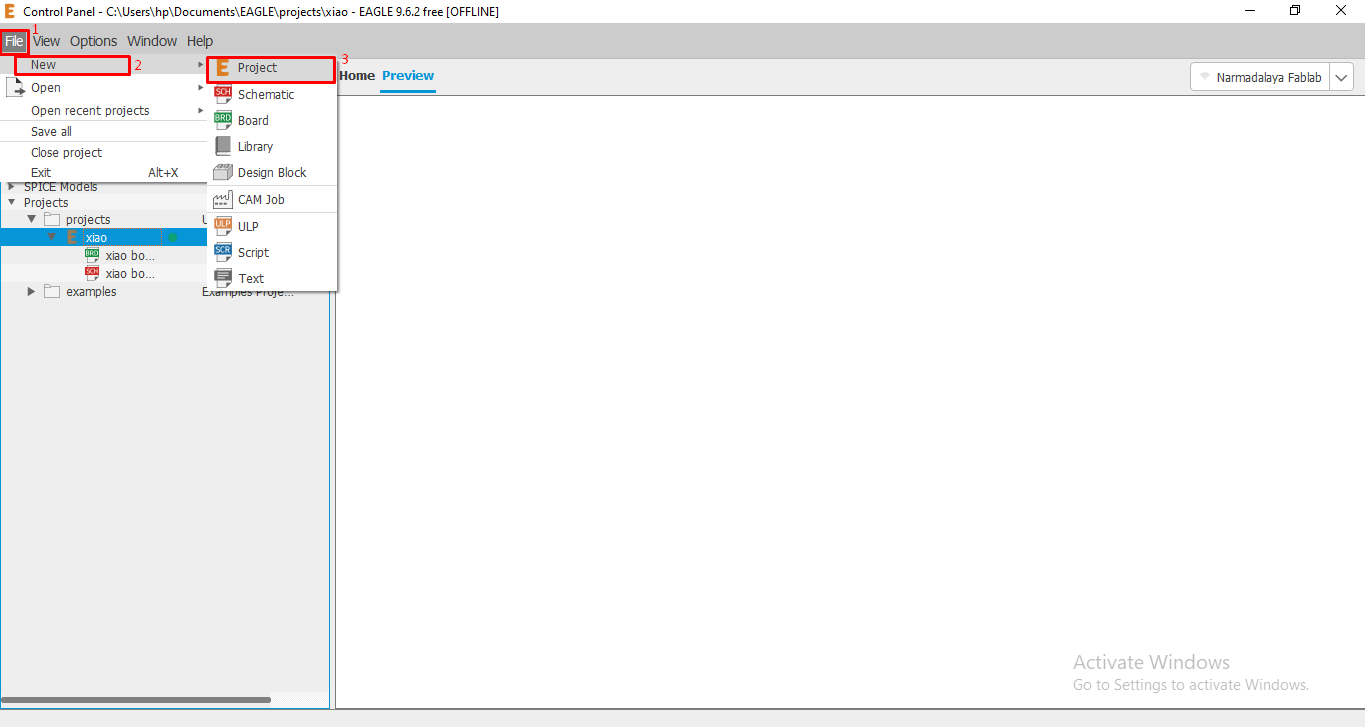
Then a new window open. Here we have rename our project name. After this right on them follow this Process.
Project (right click) >> New >> Schematic.
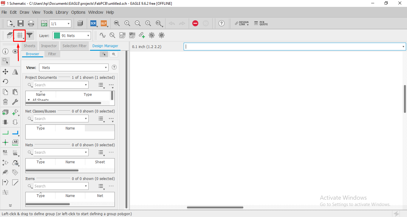
In schematic we have to add parts and add connection between the parts.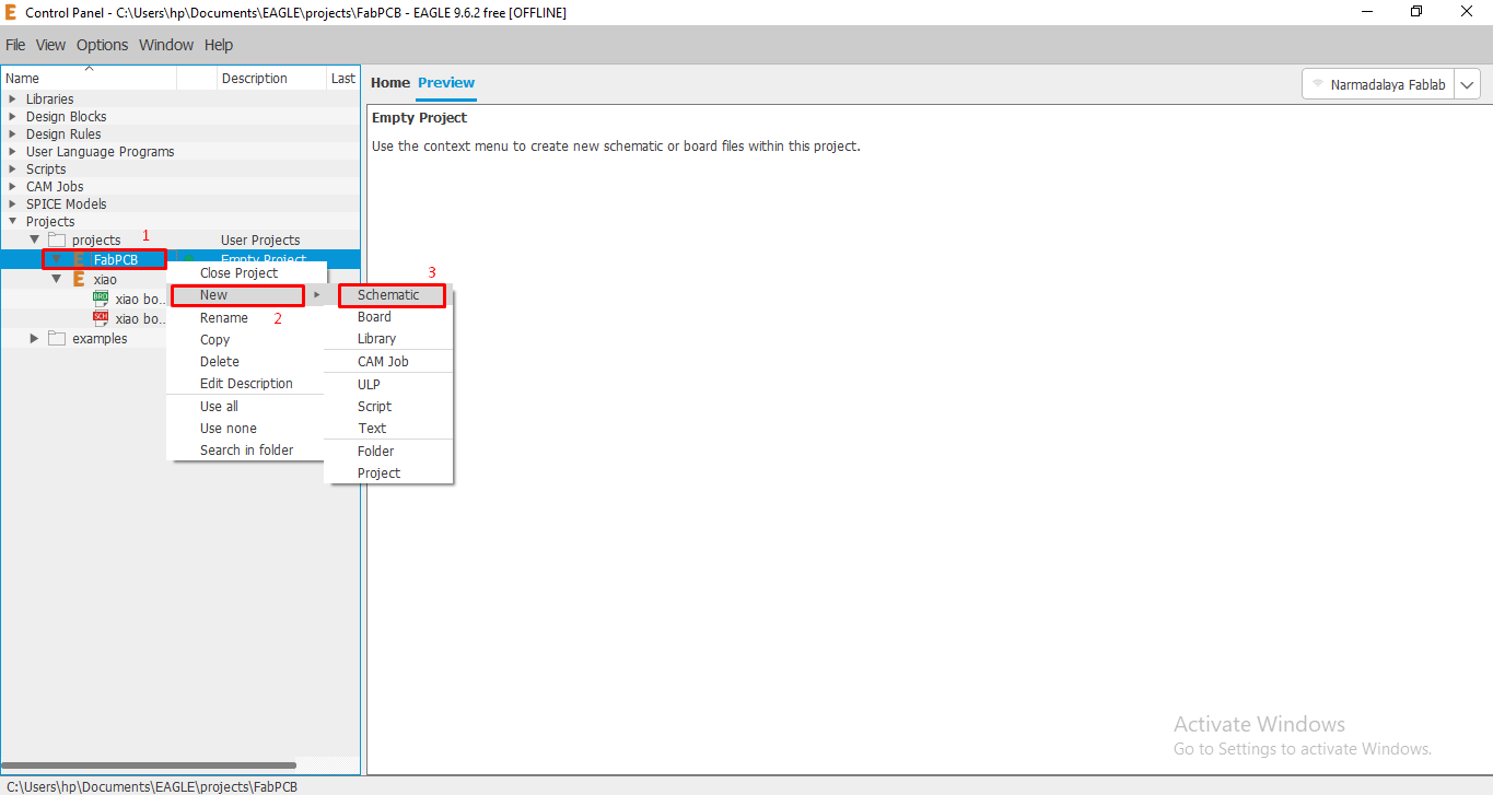
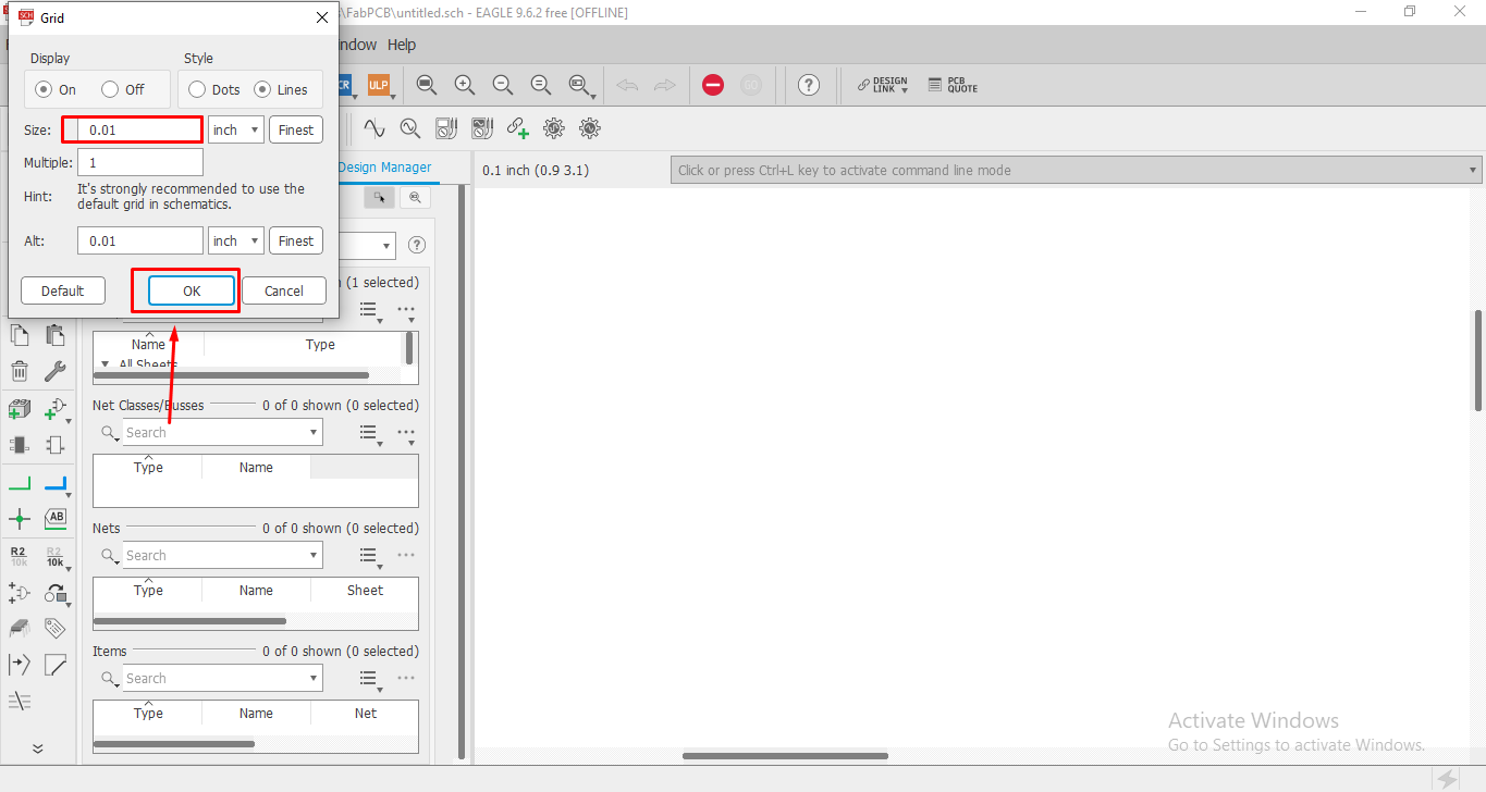
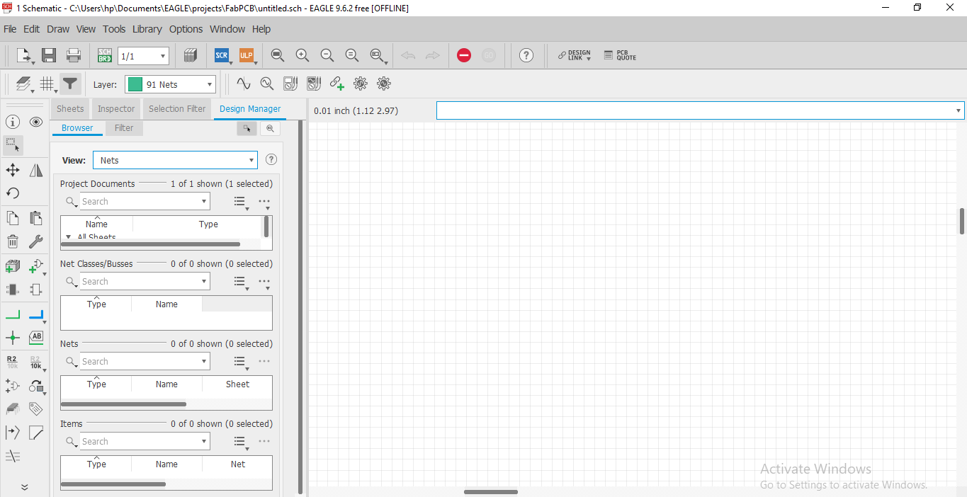
After this a New window open and we have lots of menu. First go to the grid Option and select it of size 0.01 inches. grid help us to arrange the position of the the parts.
Library update on Eagle
Whenever we have to design a PCB with new board or IC. We have to add its Library on eagle by which we can know the dimension of that board andproper positions of the pins with details.
For library update-
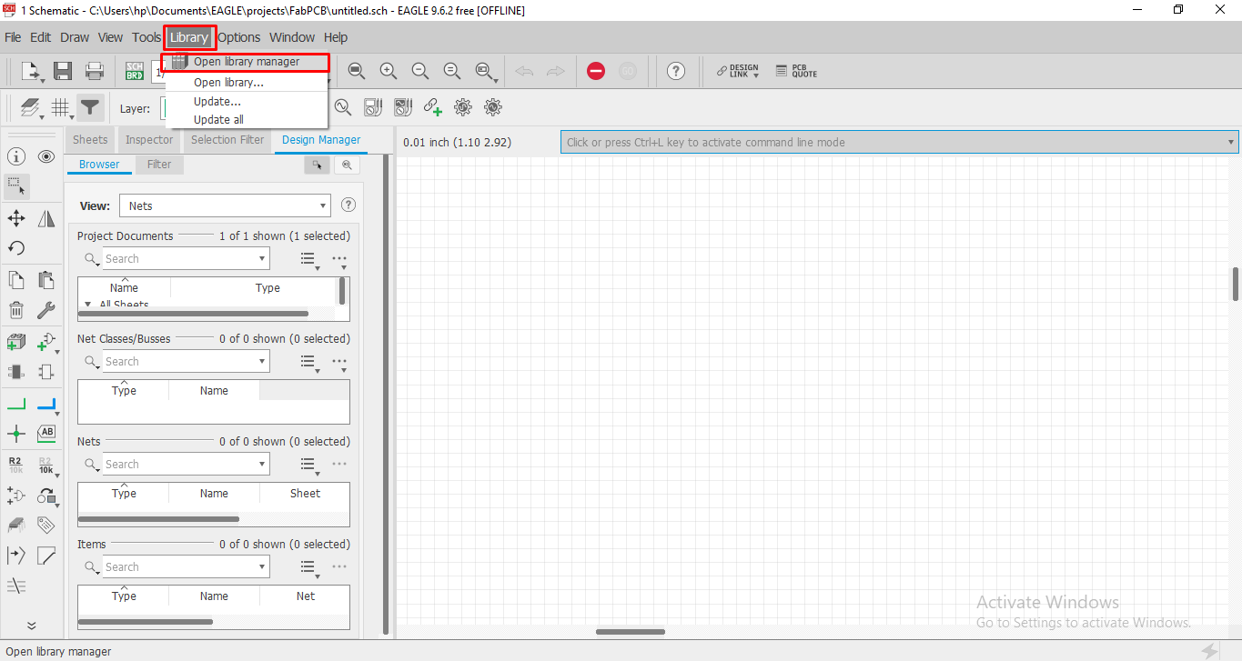
Go to Library >> Open library manager >> Available >> browse
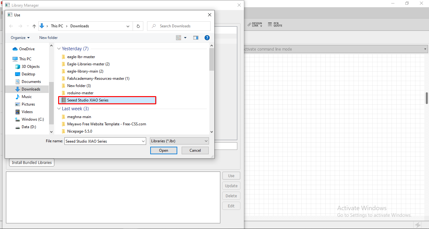
click here to download eagle library.
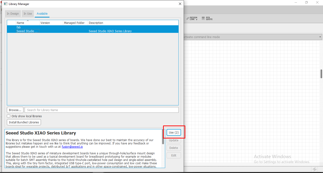
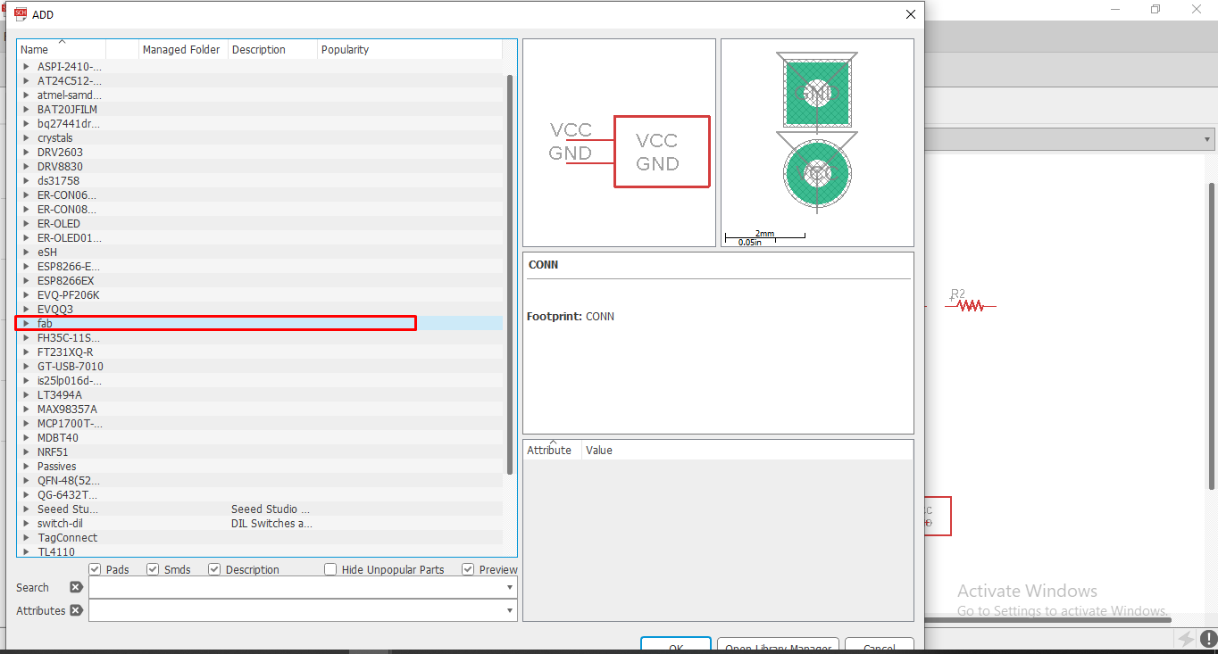
Then select the library and open it. Then click on the file and select Use. I added two library of fab and Seedstudio XIAO series.
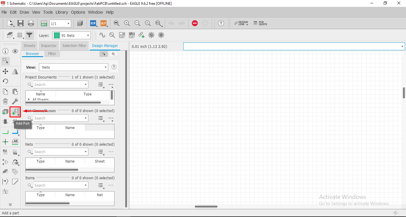
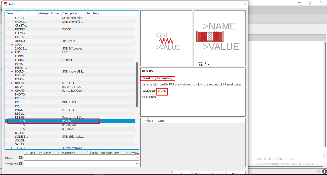
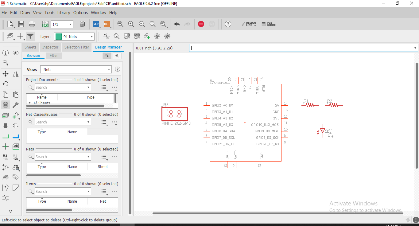
After adding library now we add the part. To select the parts go to the Add part option or simply write "add" on search bar.
Then select the parts. For this PCB I select XIAO ESP32C3 Microcontroller, Resistor and LED of Package 1206, and a Pin Holder. Resistor, Led and
pin holder are found in Fab library.
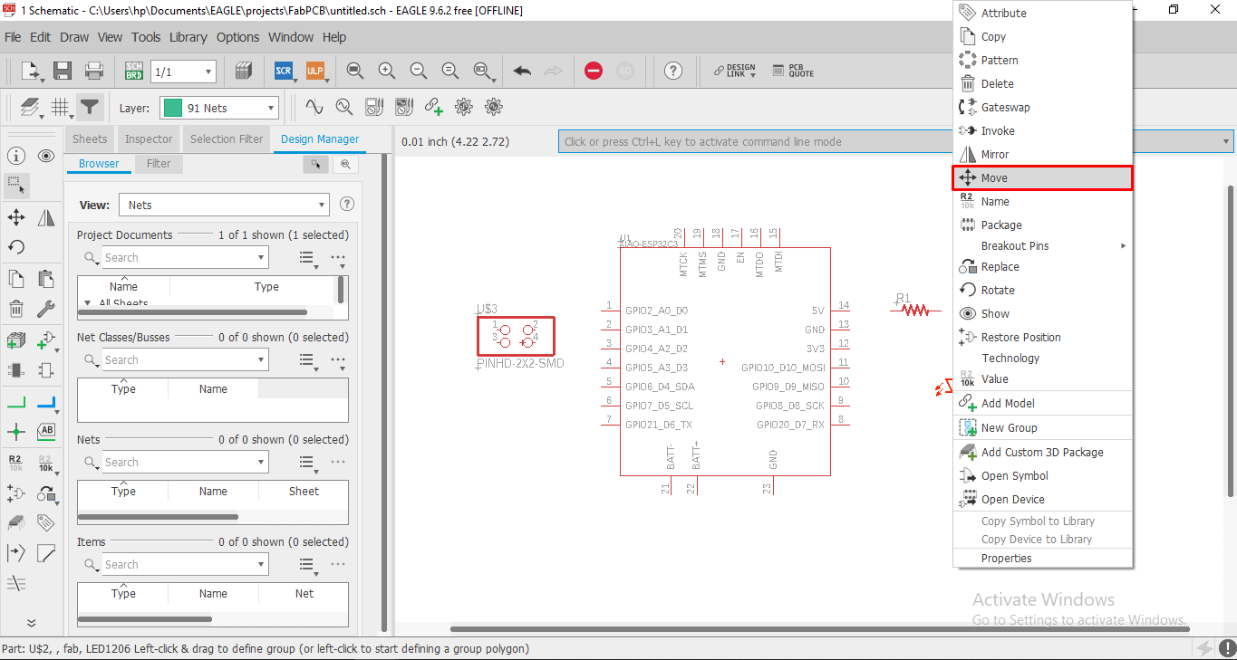
Now we have to arrange this part. Every part have plus sign in it. click and press the plus sign and then we can move the part.
When we select pllus sign and right click, a part editing toolbar is open. By this we can move, rotate , delete and pattern can be given to that
part.
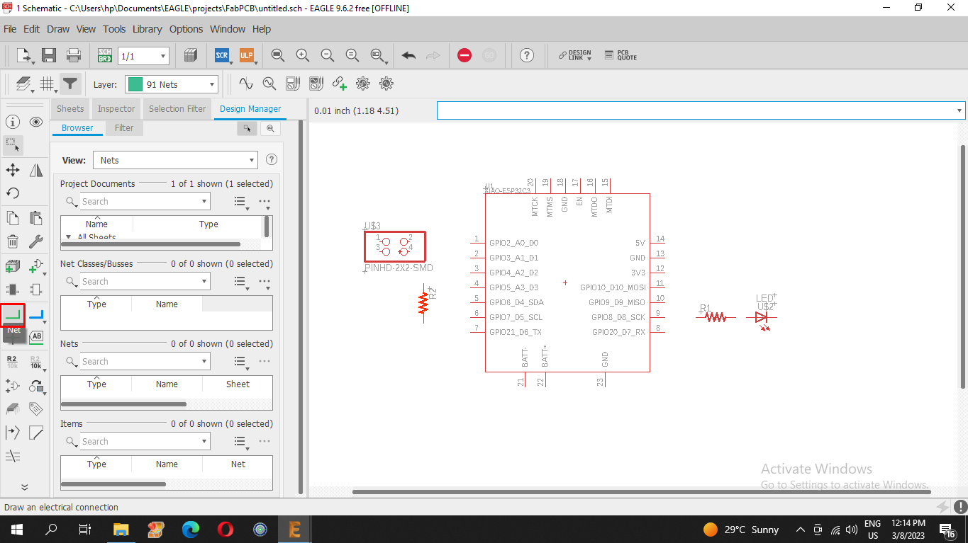
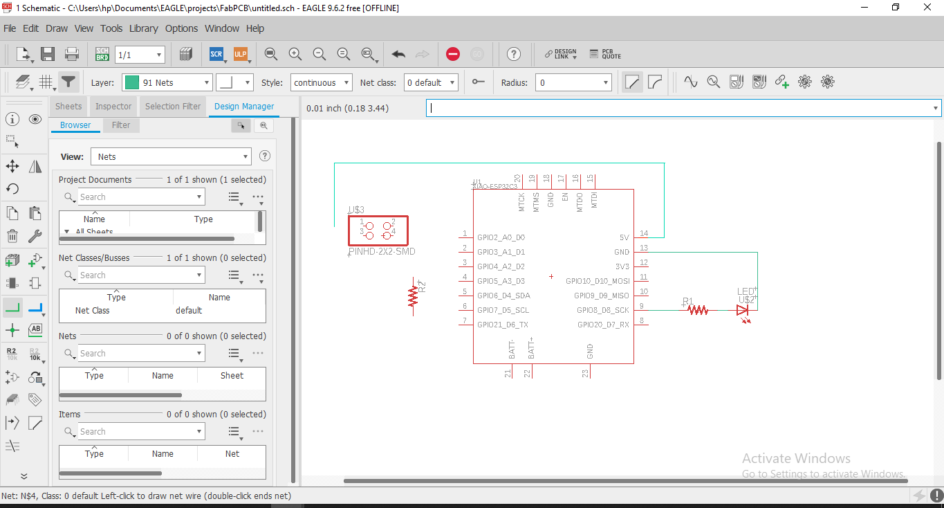
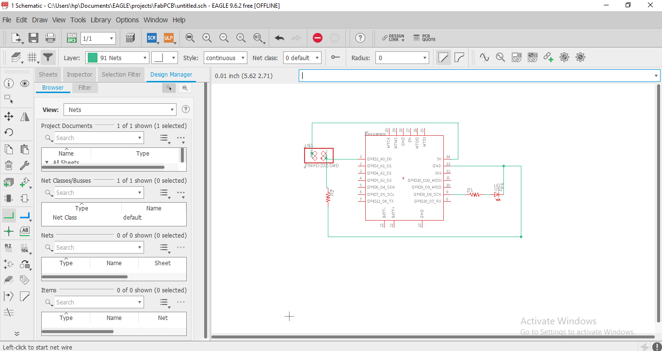
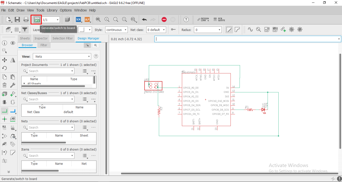
After arranging the part . Now we have to make conection between this parts. For making conection, simply go and select Net command as shown in Image
Then we simply make connection.
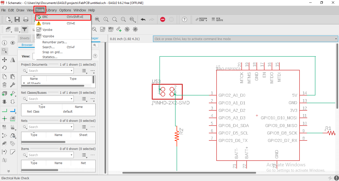
Whenever we writing a code and then we complie them for finding error . Just like that in electronic design we also have to check and follow the
electronic rule. It give error when the net is overlap and when joint are not proper connected. So for check this file
Go to Tool >> ERC (ERC is the tool to check schematic design ).
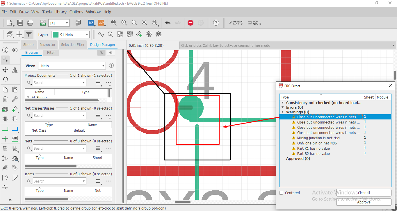
Now we getting some error and warnings at popup window.
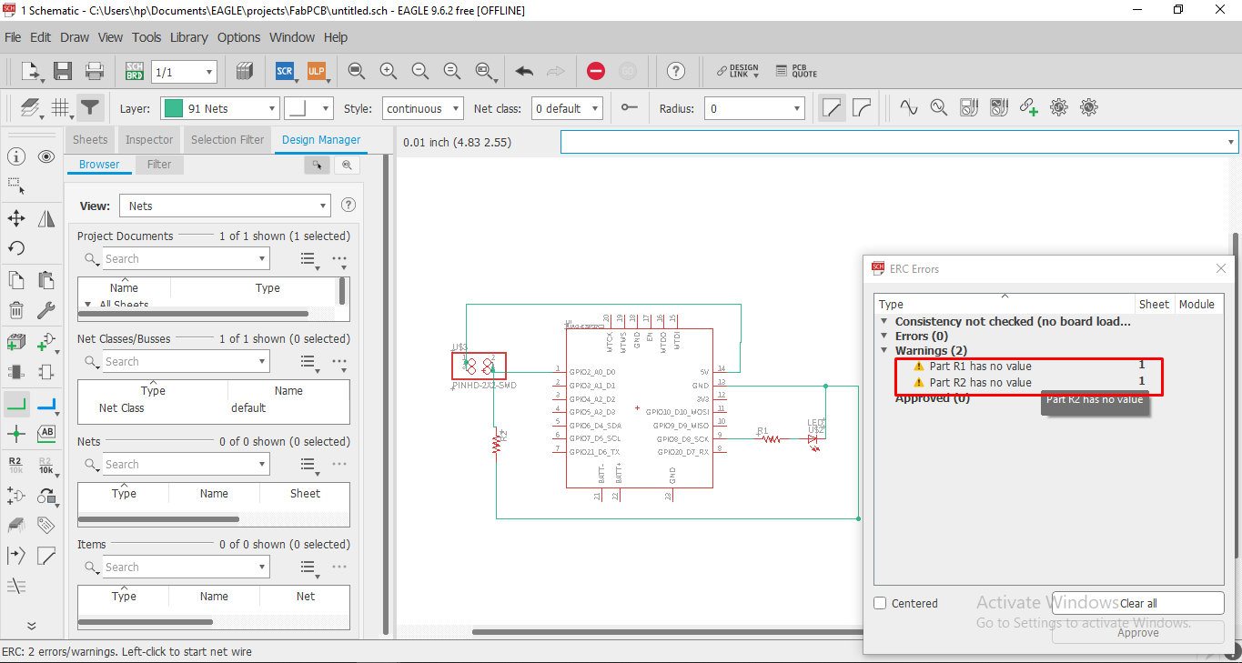
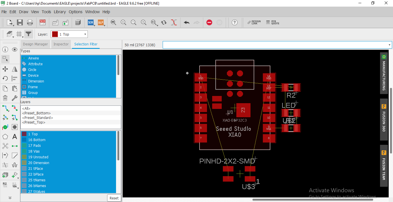
After solving all this error and warning we switch from schematic to Board. For this select option which shown in image. after this new board window is open
Schematic to Board
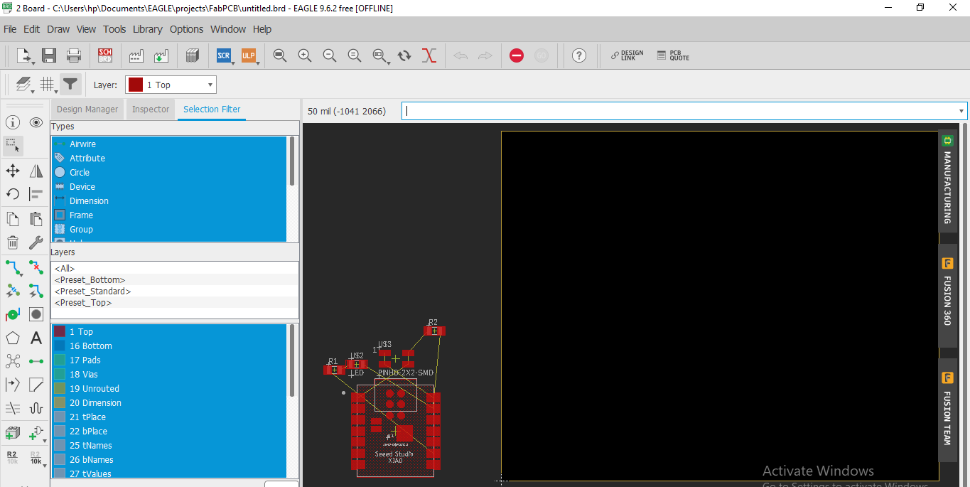
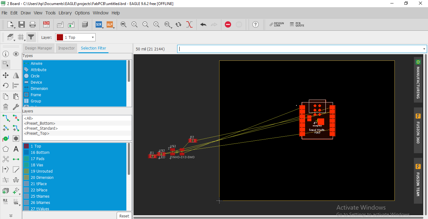
One by one select the part by clicking on its plus sign and drag them into rectangular box
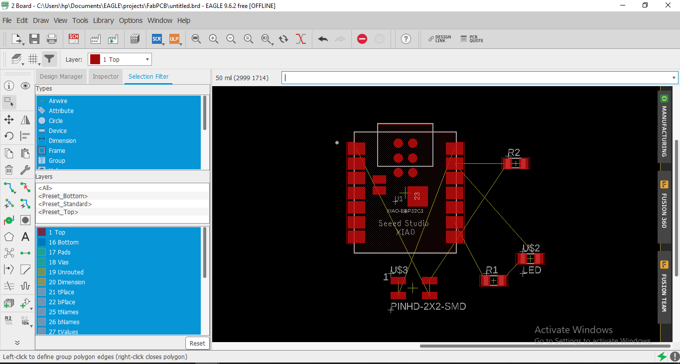
We arrange this part in proper way. This is the final position of the parts in Board
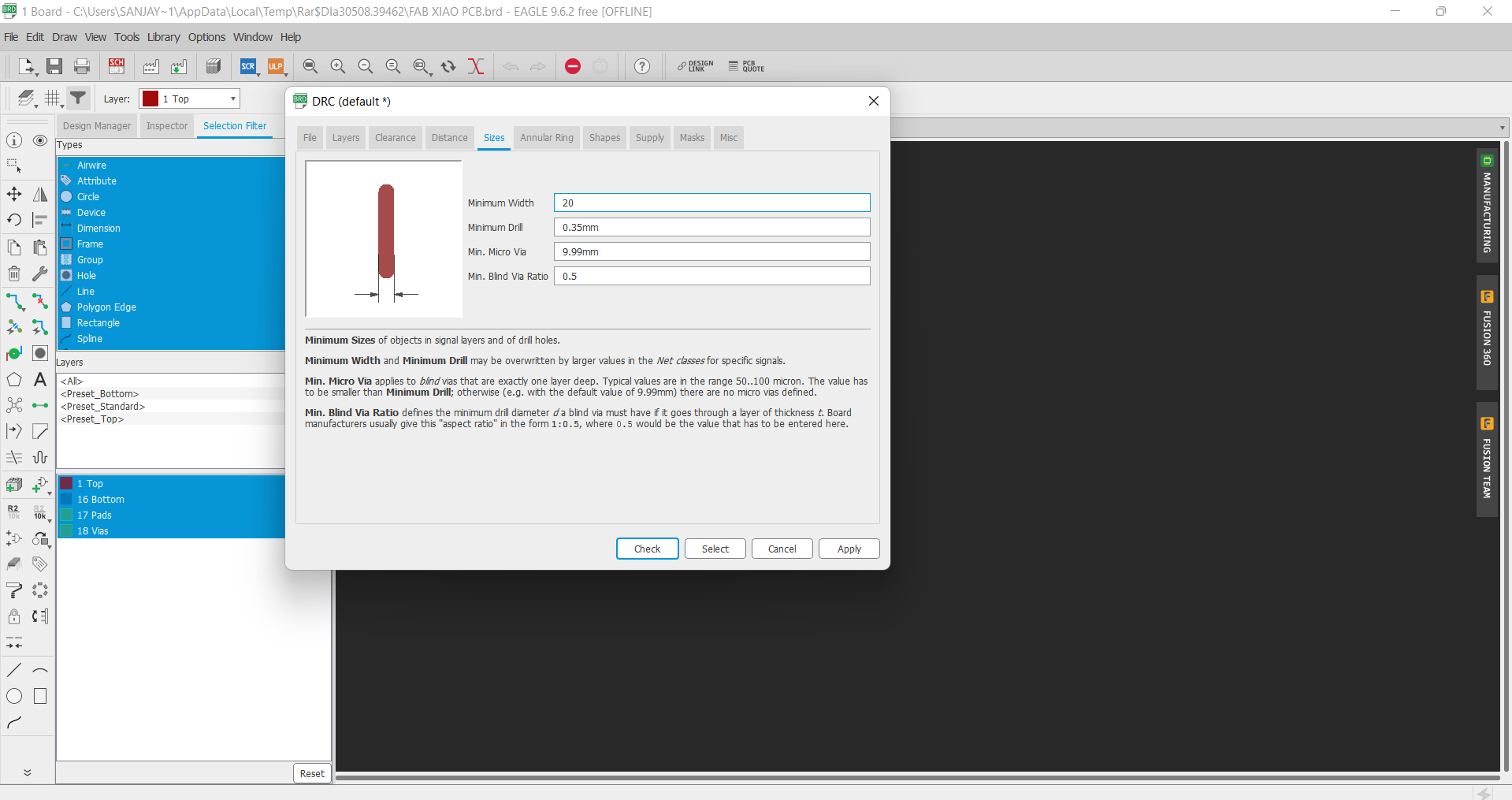
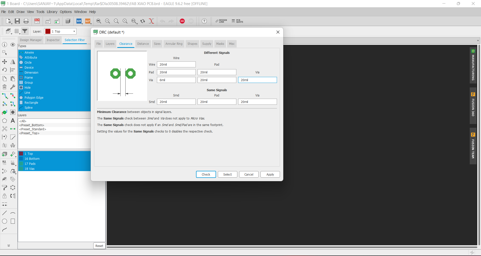
Just like schematic we also have a DRC in eagle which is a Design rule check tool. Here we can set the clearnce between two patways, Size of the pathway and
many more. To calculate the width of traces according to current value flow. So we used a online PCB width calculator. we calculate the width for 1A current,
Beacuase we use only LEDs in the board which requirde current under 1A.
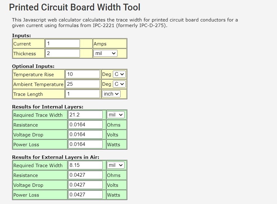
After calculation, We have to set the trace width of around 20mil. So go the tool and select DRC here.
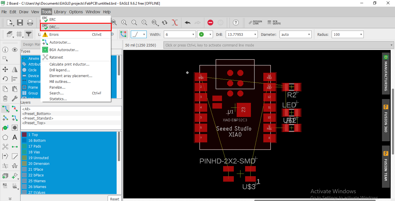
Now I change the value od width and other parameter.
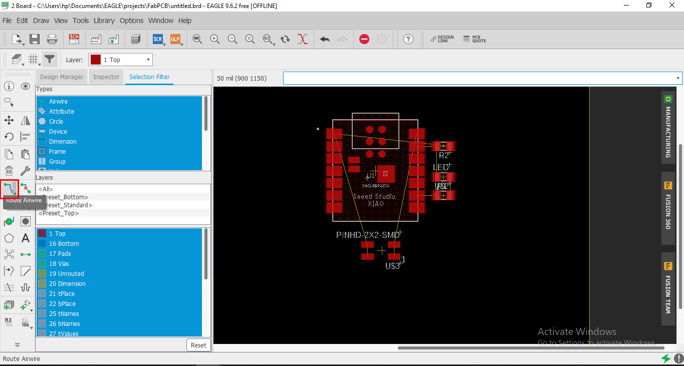
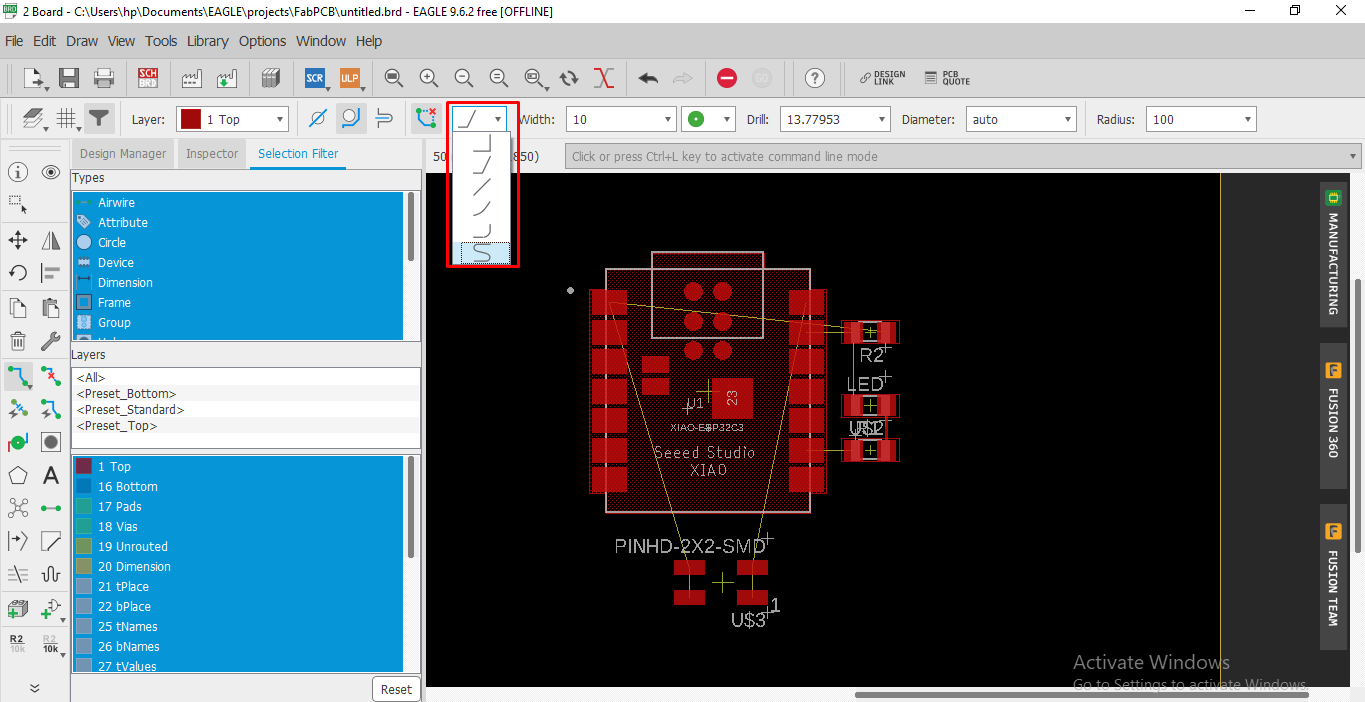
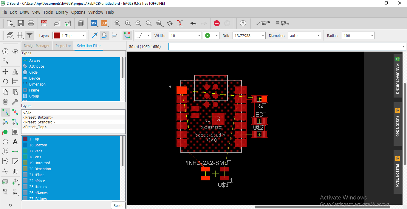
Now we have convert into a pathway . Here yellow line are help in traces the pathway. For this select route airwire and start to make pathway
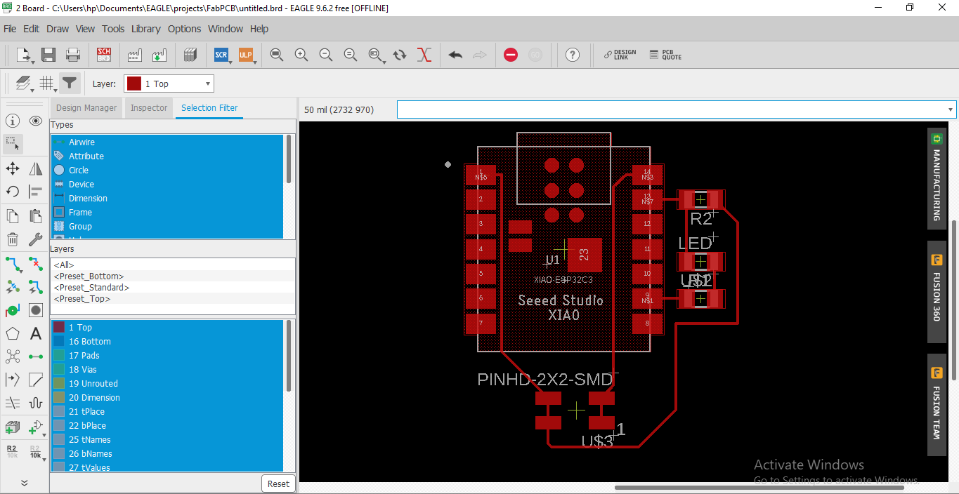
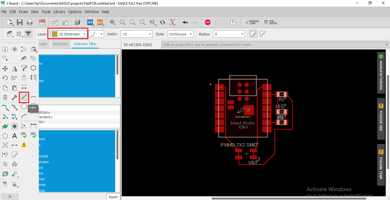
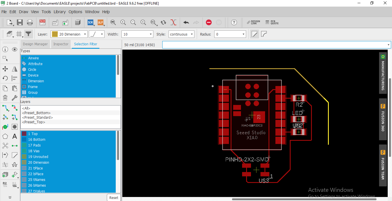
Now We have to make border of this board. For this select dimension in layer and then select line and start making the border
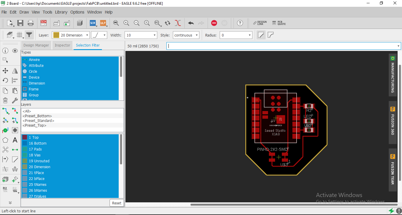
Now the design of the PCB is raedy. We have to export this PCB in PNG formate.
Design export in PNG
Now we have to export this design file PNG formate. We need two separate file for PCB production. One is traces milling and another is bordercutting. So firstly we export the file file for the Traces milling.
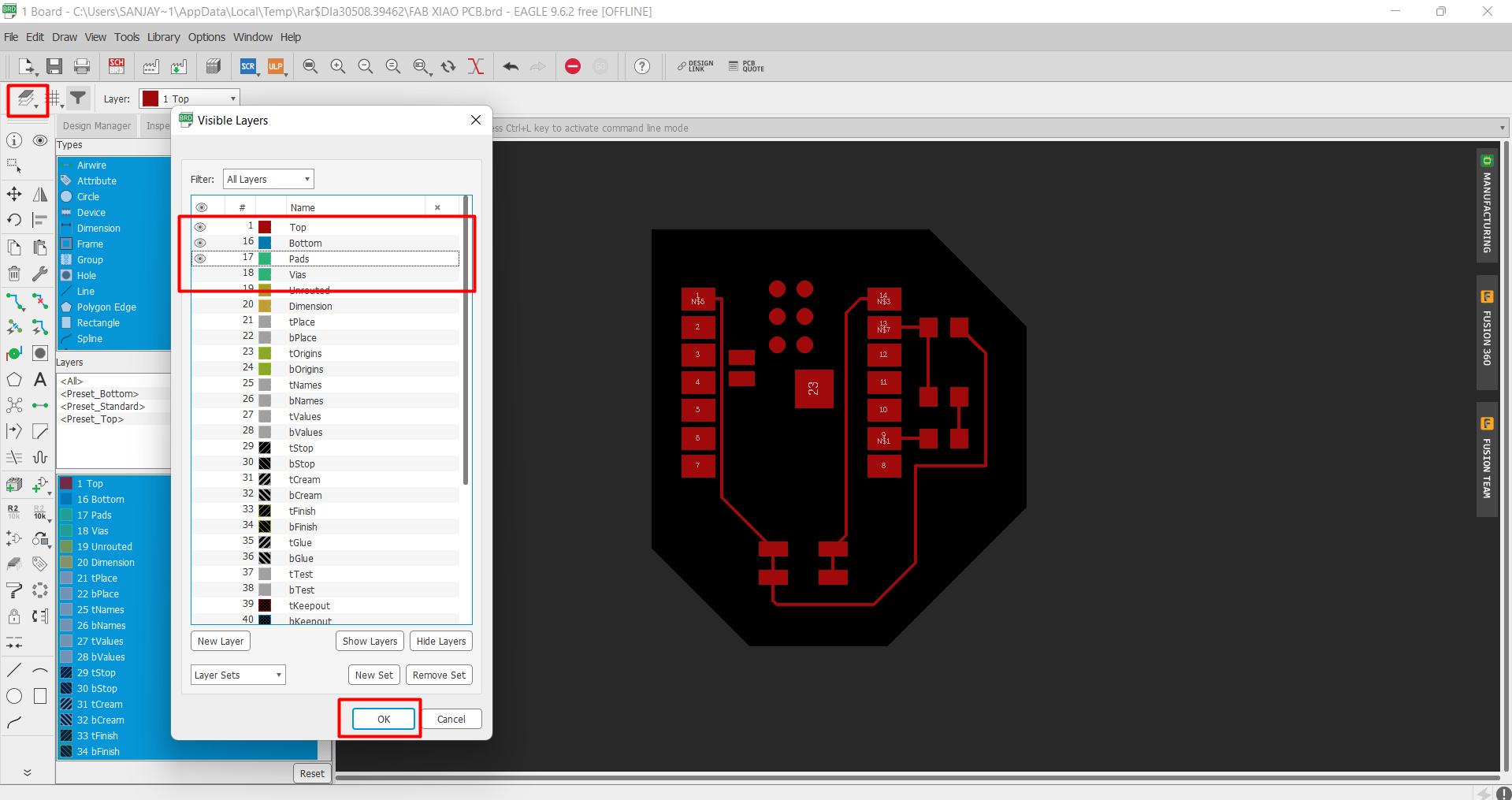
So go the Layer option and Hide all the layer, then make visible top, bottom and pad layer and then click on OK.
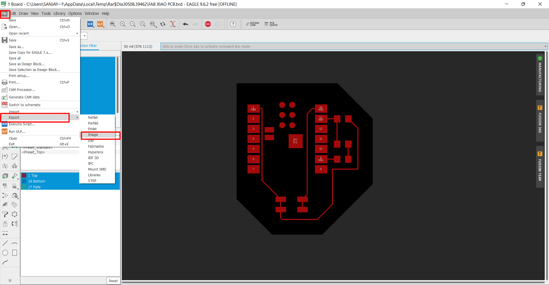
After that go to the file option and select the export option. In export option select the Image option
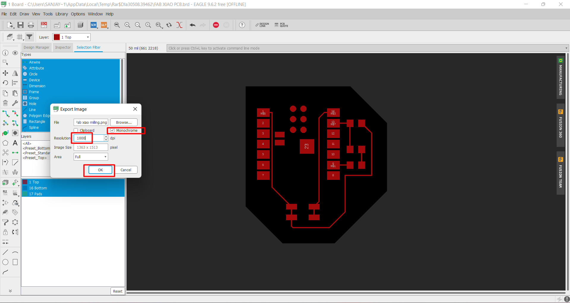
Then select the file name and browse the location where you want to save the file. Then check the box of monochrome and set the resolution of 1000
and then click on ok. PNG file of milling is saved .
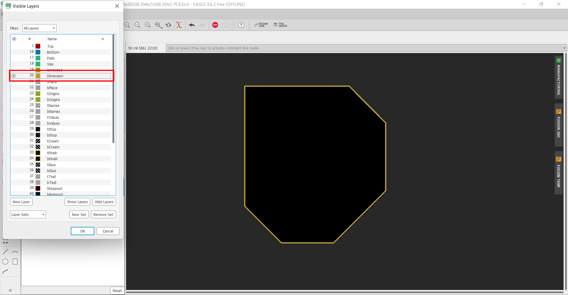
Now we have to eport design for cutting oprtaion. So again go the layer and then hide all layer and make visible the dimension layer.
Then again go to the file and select export option and then select Image option. Now select the file name , browse the location
click on monochrome and and set the resolution of 1000 and then click on ok.
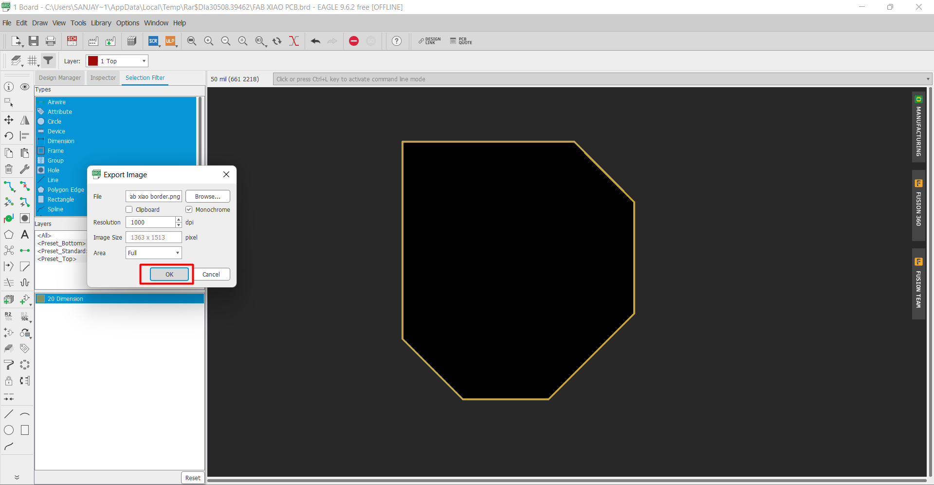
Now the PNG file for border is saved.
Learning outcomes
-I learned about the different type of instrumnets of lab-I learned about a new type of microcontroller XIAO.
-I learned about the electronic design